Boatanchors.
It's time to reduce the over-large "collection" I have acquired of older shortwave radios. Mostly tube-type (also called "hollow-state") general coverage models. Here I have a list of them. They're often known as "boat anchors." In fact there is even a newsgroup about them, rec.radio.boatanchors.
Protect your tube filaments! Check my "Tube Saver" page for instructions and parts list.
Short Wave Listening.
I've got several receivers but right now I'm mainly using the cheapest one! It's a Realistic DX-200. And actually I find it to be pretty decent. And I found out that you can still order a service manual for it from Radio Shack. Note that there are NO operator instructions in THIS manual! Simply stop in at your local Radio Shack store and ask them to order Stock Number 1128-8313. It only costs $6.65 plus $2.00 for shipping, and then add your local sales tax. It has lots of parts information and alignment procedures, too.
I received enough questions about the DX-200 to make me establish a
DX200 web page for it!About the beginning of December, 2000, I got a TenTec RX320 and I'm just getting started using it. I've dedicated an old 486 PC to use with it and it's taking a while to get that all set up. And more time to work out a good antenna. There is a lot of very interesting, useful software around for use with the RX320. It's really convenient to have a database essentially built into the radio!
Later on, I picked up another motherboard like the 1996 Pentium one in my "main" computer and so I put it into the case that held the 486. I'm using KF5OJ's RX320 program, Tom Lackamp's Scan320 program, and occasionally I use Gerd Niephaus's GNRX320 as well. They're all good and all are fun to experiment with. Another interesting one, the latest I've tried (September, 2001) is by George Privalov. He's developed a way to use the RX320 line output connected to the sound card line input to lock the receiver's frequency to the transmitter frequency and essentially generate a synchronous detector.
AM Broadcast Band listening and DX'ing.
So far this consists of listening to the Grand Ole Opry on my GE Superadio. I have done some listening in the evening to find out how many stations I could hear and identify. Identifying them is why I started learning about adding a digital frequency readout.
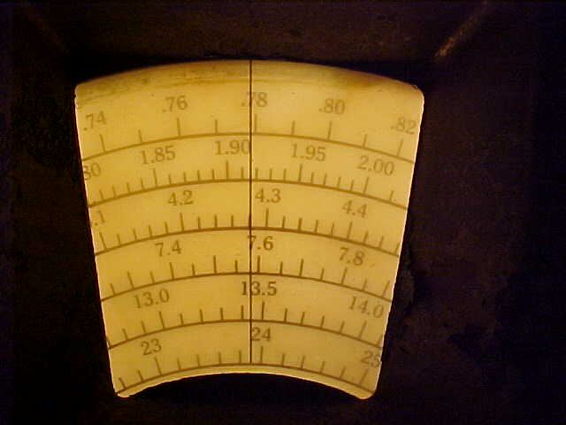
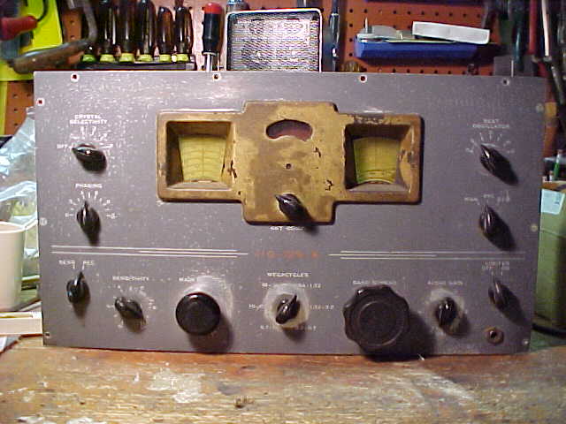
Early in the Winter of 2000 I finally fired up an old Hammarlund HQ-129x 11-tube receiver that works really nicely for AM BCB because it's got pretty good selectivity, great sound quality (requires external speaker) and its dial is calibrated every 10 kHz in the AM BCB so it's easier to identify stations that I hear. It's hooked up to a 350-foot long piece of wire that runs straight west out of my basement radio room, about 5 feet high thru bushes and trees out into the woods next to the house. There's a description of the installation on my new Wire Antennas page. Pictures of the HQ129 tuning dial and front panel are posted too.
AM Stereo
In reading about synchronous detectors I ran into some information about AM Stereo decoders. Then I got to reading about AM Stereo broadcasting in its own right. There's a great AM Stereo Page web site. Anyway I wanted to try it so I went out and got some old car radios which can receive AM Stereo. Now I've got to set up one or two as portable radios and see if I can find any local AM stations broadcasting in stereo. For anyone else who might want to try it, all the Chrysler products digital car radios from 1985 to 1992 can receive the AM Stereo and they have the MC13020 decoder chip in them. I checked mine! But they don't say anything about their stereo AM capability on the front panel like the Delco and Ford and Mitsubishi units that I've seen do. I paid $5 at a junkyard for the radio from an '86 Plymouth Reliant. However, I also paid $20 (wow!) for a fancy Mitsubishi "computer controlled" unit with 9-band graphic equalizer, cassette deck, and other fancy features. I bought it and a $10 Delco that also has AM Stereo from a shop that sells and installs custom car stereos. These were good radios that were removed from active service so I wasn't gambling on whether or not they would work. All these radios are from the mid to late eighties. After about 1992 or so, AM Stereo radios seem to have become less available. There used to be a picture of the Delco radio front panel on the "Radio" page of my Club Photo Albums List Page but they deleted all my pictures.
I found circuit information for AM Stereo decoding circuits using the MC13020 and similar chips at www.mot-sps.com/lit/html/an-hk-07h.html and at www.protel.com/library/psd_mocsster.htm.
There was an article about the C-QUAM system at http://www.inetarena.com/~alfredot/exciter-theory.html He describes the operation of the receiver circuits too, including the use of a Synchronous Detector. Here's a quote:
Most of the AM stereo tuners built during the 1980s used Motorola's MC13020 integrated circuit, which contains some rather elaborate pilot tone detection circuitry.
I found the 12 page Motorola Application Note AN-HK-07, "A High Performance Manual-tuned AM Stereo Receiver for Automotive Application Using Motorola ICs MC13021, MC13020 and MC13041" on the web at one time and printed it out, but did not save the PDF file. Now the older Motorola documents are gone from their website so I scanned the article to post in DjVu format. It's an-hk-07.djvu and is 304KB. It covers the design of a car radio, including schematic and PC board layout, typical operation of the various circuits, but does NOT include specs on any chips.
Experimenting with radio circuits and antennas.
Mechanical Filters
I acquired a Collins Mechanical Filter, although I don't remember when. It's a model F455FA-21 SSB filter, as was used in the 75S3, 75S3-B and 75S-C receivers, the 32S series transmitters, and in the KWM2 transceiver. Its bandwidth is 2.1kHz @ 6 db. and 5.3kHz @ 60 db. However, I don't have any need for one with that bandwidth, but I'd REALLY like to have one with a bandwidth for AM reception. Something in the 4 to 6 or 7 kHz. range would be ideal. So I'm hoping to find someone who would like to swap!
Projects
Projects I have under way are to add digital frequency readout to a GE Superadio III, and maybe add a synchronous detector. I've also made an indoor loop antenna that works wonderfully well on the AM Broadcast Band, although I don't use it with the GE SR3.
I also gathered some information on doing the radio alignment procedure from the GE SR3 factory service manual.
Digital Readouts
Shortly after getting out the GE Superadio and reading the FAQ statements about its poor dial calibration, I ran into the Almost All Digital Electronics web site, selling a very flexible digital frequency display. The AADE site has an "Application Notes" page describing how to connect their display to the Superadio. But I wondered also about building one on my own, and cheaper. Then I happened to find an article called "Add a Digital Dial" in an old Summer, 1985 Hands On Electronics magazine from my collection.. So I started checking on finding the parts to build the dial. The basis of it is the National MM5430 integrated circuit. The MM5430 was a clock, counter, decoder and display driver all in one and connected directly to the 7-segment displays. But I can't find any info on it any more and I think it must have been discontinued some time ago already.
So I went to the library to check in my favorite How-To bibliography, some big, yellow soft-cover books called "Index to How To Do It Information," published by Norman Lathrop Enterprises, PO Box 198, Wooster, Ohio 44691. There are about 5 volumes covering 1969 to the present. It's like the "Reader's Guide to Periodical Literature" that all libraries have, but this one is just for how-to magazine articles (of ALL kinds!). All I could find, though, was "Build an AM/FM Frequency Display" in the March and April, 1978 Radio-Electronics magazine. I looked at the library's microfiche copy and printed a couple of pages including the parts list. This one is based on the General Instrument AY-3-8112 chip with the same features as the National MM5430. But I couldn't find any info or source for this one, either.
The FAR Circuits web site shows them having a circuit board or two for digital displays as well, so I checked the corresponding magazine article in the library microfiche. QST for January, 1980. It also appears to be pretty old and quite likely use parts no longer available.
Then I realized that a few years ago I had bought a very cheap car stereo that had the same type of display I was looking for. It used a mechanical tuning mechanism and variable capacitor oscillator, not a synthesizer, but had a digital frequency display and clock. Unfortunately I couldn't find that one, so I went looking for another. I got a very similar unit from a local shop that specializes in car audio systems. It had been removed from a car and replaced with something better. So it was very cheap! I opened it up and started examining components and tracing wiring. It also has a chip that works like the National and G.I chips, but it's the Sanyo LC7267. A very convenient thing about the Sanyo chip is that its spec sheet is available on the web, thru Sanyo's site, as a PDF file that I downloaded (from http://www.elisnet.or.jp/login-sanyo.htm) and printed. The apparently I lost the downloaded file. It is 7 or 8 pages, with pinout, descriptions of the uses of each pin, and best of all, sample circuits. And of course the radio also already had a 3-1/2 digit LED display, already connected to the clock/counter chip. I need to choose and build a preamp circuit to make the rather low level oscillator signal from the GE large enough for the counter, and then work out a way to mount the parts. I'll probably have to put the display outside the radio. Maybe in a small box under it, with the synchronous detector I'm also hoping to make. The sync det plan in recent ARRL handbooks looks very promising, and I got that complete article from an older QST from the library microfiche too.
Synchronous Detectors
Synchronous detectors seem fascinating. Nearly everyone who writes about using one claims they're great. I've never heard one but have wanted to try building one. I haven't actually started building or even finding parts yet, though. So far it's hard to pick out which one to start with. Here's the information I've been able to find about them.
The sync det plan in recent ARRL handbooks looks very promising, and I got that complete article QST from QST, July 1993, page 28 from the library microfiche too. It uses an NE-602 and an NE-604. The article, by OH2GF, is about six pages long. In a sidebar, WJ1Z describes his testing the project with a Drake SW-4A and an IC-729 transceiver and said that it worked out very well. The original project added the sync detector to a Sangean ATS-808 portable receiver.
FAR Circuits has a $5.25 board for the Sync Det in the Fall, 1994 Communications Quarterly 13-page article by Scott Prather, KB9Y entitled "A Unique Approach to AM Synchronous Detection." It uses the Motorola MC13022 AM Stereo Decoder chip, a 4066 I.C., 2 transistors and an LM311 Audio Amp I.C to drive the speaker. He says that the receiver must be very stable. I hope I won't get in trouble for scanning and posting this article as a 184KB DjVu file. It's a very good article!
NOTE: It's posted as a DjVu file, which requires a free browser plug-in available from http://www.lizardtech.com/ in order to view it.
I found the MC13022 spec sheet online as a PDF file at
An 8-page article called "Synchronous Detection of AM Signals: What is it and how does it work?" appeared in the September, 1992 QEX magazine. It has several pages of the theory of amplitude modulation and then goes into the demodulation. The circuit uses the Sony CX-857 stereo decoder and PSN phasing amplifier chips that are used in the "famous" Sony ICF-2010 synchronous detector. The author of the article, Mike Gruber WA1SVF, an ARRL Laboratory EMC/RFI Engineer, reports that Steve Johnston, WD8DAS sells a kit for building it and has more information on his web site at http://www.qsl.net/wd8das/syncinfo.txt. WD8DAS also has a copy of a 2-page review from the October, 1994 issue of Electric Radio magazine. I have received permission from the ARRL to post a scanned copy of the article.
Reprinted with permission from September 1992 QEX; copyright ARRL. Here's the link QEX 09/1992. (99k)
NOTE:It's posted as a DjVu file, which requires a free browser plug-in available from http://www.lizardtech.com/ in order to view it.
ARRL does provide reprint service. Cost for reprints is $3 per article for ARRL members, $5 per article for non-members. Requests should be sent to reprints@arrl.org or addressed to the Technical Secretary, ARRL, 225 Main St, Newington, CT 06111.
While looking for other info about the Sony CX-857, I found a web page in another language with a GIF of a stereo decoder circuit using the MC13020 at
http://www.jimcom.net/elehobby/syncdet/amsync.gif
And someone who had asked earlier (a year ago) for MC13020 specs sent me a link to the "archived" version (800KB), which is at
The web page synch det bibliography (which was) at http://www.primenet.com/~ctrask/syncdet.html says that there's a Popular Electronics article by Dave Hershberger entitled "Build a Synchronous Detector for AM Radio" on pages 61-71 of the April, 1982 issue.
That Popular Electronics article is very informative. It explains a lot about the principles of AM and detection, and what causes the problems with fading and distortion. It explains very well the theory of how this synchronous detector works, how to build it and how to set it up and align it. It works with a fairly wide range of signal levels and includes the phasing circuitry for selectable sideband operation as well. In fact, selectable sideband circuitry is optional and can be left out. The primary active parts of the circuit are an MV2115 Varactor diode, three 2N3904 transistors, an LM318N op amp, 3 TL074CN quad op amps, a TL072 dual op amp, and two CD4053BCN multiplexers. The phase detector itself is a 74C932 but that is described as possibly hard to find and instructions show how to substitute a CD4046 PLL. There's also a zero-center tuning meter. A switch selects two different loop time constants, to make it easier to tune in the signal and then to keep the detector locked even when the signal fades very deeply. All in all, I thought it was a pretty impressive article, and very comprehensive. Especially for a mass-market hobby magazine.
> NOTE: The article has a published correction in the July '82 issue of
> "Popular Electronics" on P. 6
in Fig. 4, pin3 of IC8 should be connected to pin 11 of IC2
not pin10.
and an unpublished correction where the "ENV"
> (i.e. Envelope Detector) position of switch S1B should be ground (GND) not
> N.C. as shown
I posted the PE article here: PE_sync.djvu NOTE: It's posted as a DjVu file, which requires a free browser plug-in available from http://www.lizardtech.com/ in order to view it. And it's BIG at 822KB so it will take a long time to download. Be sure to save it on your hard disk!
More information on the theory of synchronous detection from the July 1982 issue.
In the something different department: some notes from another person interested in synchronous detectors.
There was a synch det project online at http://members.localnet.com/~wa1sov/technical/sync_det.html too. It uses only an LM311 op amp and an AD607 product detector. It looks pretty simple. The schematic is on the site, but it prints out too wide for my printer so I haven't seen the whole thing yet. Check and see if it's on line now. I did see it on November 10, 2002. There is an architecture description of the AD607 at http://www.analog.com/library/analogDialogue/archives/29-2/ad607_art.html
I don't know if it's still available, but Plessey (also known later as GEC and then Mitel) made a chip for multimode reception that has been used as a synch det, too. It's the SL1624. A circuit for it was shown in their Radio Communications Handbook, published in 1977. I have a scanned copy of the page from the book. It's posted as a DjVu file, which requires a free browser plug-in available from http://www.lizardtech.com/ in order to view it.
There is a small, simple, basic example circuit for a synch det using a CA3006 on page 375 of Ulrich Rohde's book on receivers, too.
In August, 2002 I received a scan of a synchronous detection article from Chris in the U.K. He said:
"Found a good article in "Electronics World" ( formerly Wireless World )
on Homodyne and Synchrodyne AM receivers
"Synchrodyne/Homodyne Receiver"
Micheal Slifkin and Noam Dori
Electonics World November 1988 Volume 104 No. 1751 pp947-953
Electronics World article in pdf format is now attached (500k). Covers design
of complete homodyne and synchrodyne receivers. Some of the Motorola
chips are now difficult to find but I guess substitutes could be found.
Here is the article: Synchr~1.pdf (516KB).
A pictorial or graphic of an AM Receiver Synchronous Detector is/was on line at http://www.shu.ac.uk/ocr/teaching/ppp/AMnoise/sld007.htm and part two of it is at http://www.shu.ac.uk/ocr/teaching/ppp/AMnoise/sld009.htm . There's as much math as graphics in the two slides.
An article entitled "Synchronous demodulation - What is it and why is it used?" by Ian Poole is posted on line at http://www.radio-electronics.com/info/receivers/sync_det.htm No circuit examples, but it does give a basic description of the theory and operation, with a block diagram.
"
The Ultimate Homebrew Receiver? Not Quite! by Nick Hall-Patch " which appears at http://www.carcanada.net/dx/homerecvr.html uses an Exar XR2228 analog multiplier IC for its synchronous detector. The article has a block diagram of the receiver, but no actual schematic. He says "This type of detector is easier to build and to use than a PLL synchronous detector and deals better with weak signals than some PLL designs. "It may give project developers some ideas, if we're lucky.
There's an ATV page at http://www.ussc.com/~uarc/utah_atv/if_filt.html
Which says
Nowdays, the vast majority of analog televisions use a synchronous detector. This is a big improvement over the envelope detector for several reasons: An envelope detector needs a good video carrier to work properly. One problem is that, as the entire video signal gets weak, the video carrier gets weaker (and noisier) as well. With the video carrier getting noisy, it adds to the noise that is already in the video from the rest of the signal being weak, making the video appear noisier than it really is. A synchronous detector, on the other hand, takes the received video carrier and reconstructs it. It can do this because, as it turns out, the video carrier can be received even though it may be very weak because the circuit that recovers it has a narrower bandwidth than the video detector itself. This is the same sort of situation where you know that there is a video signal on frequency, but you cannot see it on your TV, even though you can hear it on your FM receiver just fine. This happens because your FM rig has only about 15 KHz bandwidth as compared to the 6000 KHz (or thereabouts) bandwidth of the video receiver.
With the video carrier "regenerated" within the detector, we now have a "pristine" copy of the carrier that we may used to demodulate the video. As it turns out, synchronous demodulators produce pictures that are 6db less-noisy for a given signal than an envelope detector. This would be equivalent to the transmitter increasing its power by a factor of 4!
And there is a 2-page spec sheet PDF file for the NTE843 Integrated Circuit TV Video IF Phase Locked Loop (PLL) Synchronous Detector at http://www.nteinc.com/specs/800to899/pdf/nte843.pdf
(But no circuit diagrams or applications information.)
Now, does that give anyone an idea about other synch det sources of parts, theory or information?
In addition, there was a Toshiba TA8124 AM STEREO IC decoder, which Google shows listed on http://www.angelfire.com/biz/techsonic/page6.html
And see the note below from Andy Ikin of Wellbrook Communications.
Antenna Phasing and Noise Cancelling
Off and on I've read about noise cancelling and antenna phasing or null-steering circuits and devices. There are plans and schematics for some of them on various web sites and in a few magazines. Most seem complicated, expensive or both. But one day I found a circuit in the ARRL Radio Amateur's Library Publication #34, a book called "Radio Frequency Interference" by William Lowry and published in 1978. Go to my NoiseCanceller/Phasing Page to see my unit and its schematic.
Loop Antennas
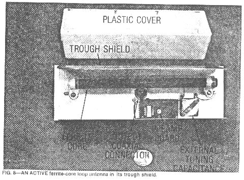
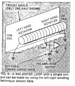
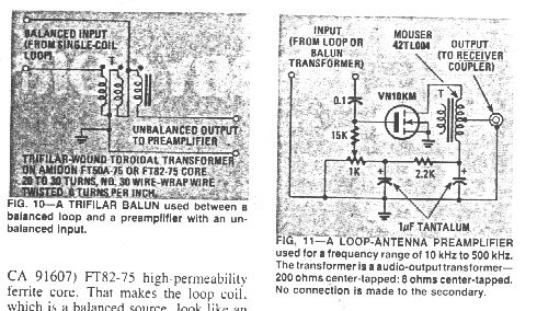
There was a really good, practical, educational article on Low Frequency loop antennas beginning on page 83 in the June, 1983 Radio-Electronics Magazine. It's called "Loop Antennas for VLF-LF" and written by R. W. Burhans. The title says VLF, but it applies very well to HF as well. There are some loop antenna projects described, and pages 2 and 3 also have great information on shielded loops, a particular interest of mine. I could only find the article on microfiche at the largest library in the area. I made a copy but it's pretty bad and definitely not scannable. So I typed in the whole thing. The bad part is that I couldn't duplicate the illustrations, and I couldn't see most of them anyway. But it's worth-while even without them. Then a couple of years later, in mid November, 2001, I found an 'original' source. A library closer to home with the complete, original issue of the magazine in very good condition. So now I have scanned it. There are 5 pages and the scanned files range from 32 to 55kB. And there are 3 separate scans of figures from the article, which I scanned in "gray" mode instead of just black & white. This makes the file size quite a bit larger but the figures are not clear in the high-contrast black-and-white mode. Fig_8 is 161k, Fig_9 is 52k, and Figs_10 & 11 (combined in one scan) is 102k. Here are the links to Page_1 , Page_2 , Page_3 , Page_4 , Page_5 .
I made a shielded loop, based on a web article from BERadio magazine (scanned Page_1 and Page_2 ) and it worked out really well. That one is square, about three feet per side. It is made of about 12 feet of Belden #9513 shielded 3-pair (6 conductor) cable. Then I tried another with slightly more cable but only about one foot in diameter. It hardly picks up anything! Most recently, the end of October, 1999, I tried a third. This one is twice as long as the first, with 25 feet of cable and thus about six feet per side. It's only 4-conductor cable, though, instead of 6 so the comparison is not exact. But the bigger one picks up at least as well as the first, medium sized one. The biggest one is just wire hanging from hooks on the ceiling, though. It's not rotatable like the first. It's currently on a wall that runs east and west, so its nulls are pointing north and south. It would be easy to move one upper corner to a north-south wall and swing the loop 90 degrees.
And Wellbrook has a commercial web site selling an interesting sounding shielded loop antenna. They have some good, worthwhile information about loops, active antennas, sensitivity and intermodulation too, especially in their Review pages.
A quote from Wellbrook:
Hi Doug,
Many thanks for mentioning Wellbrook. Please could you add my URL, as not
all the search engine links are working.
Btw. Electronics and Wireless World, September 1989 published an AM Sync
Demod. It provides SSB, ISB, envelope, DSB and Quadrature detection. I have
been using this for the past 9 years with my JRC NRD 525.
Kind regards
Andy
Andy Ikin e-mail: sales@wellbrook.uk.com
aikin@globalnet.co.uk
URL: http://www.wellbrook.uk.com
Wellbrook Communications
Wellbrook House, Brookside Road,
Bransgore, Christchurch, Dorset BH23 8NA. UK.
Tel. 01425 674174 Int.+44 1425 674174
Manufacturers of Broadband Loop Antennas
[End of quotation]
I have found many good, informative, inspirational pages about loop antennas and MW DX'ing, including Werner Funkenhauser's WHAMLOG site and another one in Canada at NordicDX.
Lead-in wires
I wanted an outside, random-wire antenna to compare with the loops so I threw some 14-gage insulated wire over some tree branches and brought the end in through a window. But then I couldn't close the window. I also drove a ground rod right outside the window and used the same type of plastic-insulated wire to connect it. Now that it's getting cold out, I wanted to be able to close and latch the window. Luckily I had picked up some scrap copper foil or sheet that looks like a ribbon about one inch wide and three feet long. There were two pieces in the dumpster at the electrical contractor's building where I work. I didn't have a plan for it at the time, but it looked useful. Anyway, I cut two pieces of it about four inches long and soldered a short piece of wire to each end. Then I laid the two strips across half of a piece of clear poly package sealing tape two inches wide and maybe a foot long. Folding the tape over in half on top of itself and the copper strips hold the strips together, parallel and about an inch apart. It's a little like railroad track and ties, but only one wide plastic track and two copper ties. I can put this thin sandwich in the window and close it completely. The copper strips were installed as shorting conductors between terminals on a large capacitor or transformer which the electrical contracting company installed somewhere. It was part of packaging some large electrical device and might be commonly found in nearly any electrical contractor's scrap pile (dumpster).
Antenna Impedance Matching Transformers (Balun, Unun)
Reading all the antenna website info made me decide I should try a matching transformer between my long wire and my RX320, which has a low impedance input. The antenna literature says long wires are 400 to 600 ohms, and the low impedance input is designed for about 50 ohms. There's a new page about the transformer I made and some results of testing on the UnUn page. Warning - I put 300kB of graphics on that page so it will take a while to load.
Antenna Installation
Two recent magazine articles inspired me to improve my random long wire antenna that hangs in the trees outside the house. One is a "What's New" item in the May, 2000 issue of CQ. It's about the "EZ Hang" which is basically a Wrist Rocket slingshot with a fishing reel mounted on it. You shoot a weight with fishline tied onto it over the tree branch where you want your antenna to go and then use the fishline to pull up the antenna support rope. The other article is called "Launch your Field Day Antenna with a Flingshot." In the June, 2000 issue of QST. In this one the author mounted a fishing reel on a home-made wooden slingshot.
I combined the two and put a cheap Zebco reel from a garage sale onto my old Wrist Rocket slingshot and doubled the height of the wire thru the trees. Next I'm going to add another wire oriented 90 degrees from the original one, and much longer. It worked out really well! I do need a bit more practice though. And if you try it, there is a problem with trees that have loose, scaly bark which the thin, nylon monofilament can get caught under.
About a year ago, August 23, 1999 I found about 10 pages of hints, tips and tricks about the slingshot method of raising antennas at http://www.qsl.net/~wd8rif/text/slgsht.txt but I haven't checked back to see if that URL is still good. The information was worthwhile, though!
In November, 2000 I put up a 350-foot long piece of wire that runs straight west out of my basement radio room, about 5 feet high thru bushes and trees out into the woods next to the house. There's a description of the installation on my new Wire Antennas page.
------home -------- Click to -----------e-mail me. ------ updated November 19, 2003