Making Your Own (Surveying) Compass
I have scanned some information in old books concerning the technology and methods of making compasses. All are monochrome in GIF format and are not large, ranging from 13 to 98 kB.
There are two pages plus the cover from "Navigation and Nautical Astronomy" seventh edition, 1942, published by the U.S. Naval Institute of Annapolis. These describe the 7-1/2 inch naval compass construction. Page 1, Page 2, Page 3 (Title Page).
Two pages and the cover of HO9, Bowditch from 1938, "The American Practical Navigator" published by the Hydrographic Office of the U.S. Navy also detail the naval compass construction, but with no picture. Page 1, Page 2, Page 3 (Title Page )
"Surveying Manual, 4th ed." By Pence & Ketchum, printed in 1938 supplies seven pages on the use and adjustment as well as the construction of the old style surveying compass. Page 1, Page 2&3, Page 4&5, Page 6&7.
Finally, I have two charts of the types and properties of magnetic steels. Both are from the National Metals Handbook. One is from 1930 and the other from 1948. After that, the newer editions I've seen leave out magnet steels.
Needles
The 1930 National Metals Handbook edition's 7 page chapter on Heat Treatment Of Magnetic Steels begins:
The steels used for permanent magnets may be classified as follows: carbon, tungsten, chromium, chromium-tungsten, cobalt-chromium, and cobalt-chromium-manganese.
I don't want to get into any discussions of metallurgy, but I am looking for a good, clear, simple explanation of how magnetizing steel works. When I find something suitable, I'll post it. Basically, the steel is very hard to prevent magnetic domain wall movement. That of course also makes it more difficult to initially align the domains in the magnetizing process. Soft iron or steel doesn't hold magnetism. In fact, motors and transformers are made with a special magnetic steel designed to be able to lose its magnetism very easily because it has to reverse its magnetic polarity 60 times per second.
I magnetized my compass needles, made of used hacksaw blades and steel banding strap, by winding a coil of 12 gage wire around a cardboard tube and touching the ends of the wire momentarily to a 12 volt car battery charger's terminals. With the new needle inside the tube, it worked very well. By the way, the coil should be as long as the needle.
I have read that the effective magnetic force of the needle comes from the surface area of the needle. The president of the Survey History Museum told me that some compasses had hollow needles to maximize area and minimize weight. The heavier the needle, the slower it will respond to changes and the more friction it will have on the bearing. That friction means that as the needle approaches alignment with the earth's magnetic field and the force pushing it decreases, the needle may stop moving slightly before it reaches true north. The weakening rotational force can't overcome the friction of the pivot. The big naval compasses as described above used bundles of magnetized fine steel wires, apparently also to maximize surface area for a given weight of steel. Also, the longer the needle the more effective "lever" it becomes in having enough torque to overcome pivot friction. Plus it also gives a larger and more readable degree scale.
It may help to think of the needle as a somewhat like a weather vane. If it's across the wind, there is a lot of force to turn the vane, but as it gets more closely aligned with the wind direction there is less force pushing on it to make it turn.
Dials
I made my dials by drawing them with AutoCad and printing on a laser printer. It takes some work, but once you get the file created it's easy to revise and to print as many copies as you need.
Printing on heavy card stock, available from Office Max in individual sheets from their CopyMax department, makes a nice, sturdy compass card. Card stock is of course also available from other office supply stores such as Staples and craft stores like Hobby Lobby.
Hardware
The hard part is making the pivot bearing. I happened to have some brass rod (actually bronze brazing rod from a welding supply store) and made a couple on my metal lathe. It would be easy to do the same thing with a drill press by putting a short piece of rod in the chuck and filing the outside to shape, and drilling a hole into the end. That you'd have to do b holding a small drill bit exactly vertical and accurately centered in a vise under the drill chuck. The actual sharp pivot can be an ordinary sewing needle, which you can break off shorter if need be. The brass rod comes in a 36 inch length and costs less than a dollar.
For the 6-1/2 inch compass bearingI used 1/4 inch brass rod which ended up 5/16 inch long.This is the largest brazing rod common in welding supply shops, and I also used a 3/16 inch bit to drill 3/16 deep. The deeper the hole you drill, the better balance you get because the center of gravity is that much lower than the pivot point. But, the deeper the hole, the less the needle can tilt. So the compass has to be more level with a deeper hole, although that's no real problem with a big surveying compass which would have to be level anyway to be able to take accurate bearings. The bottom of the hole needs to be as accurate and smooth a cone as possible to give the best bearing surface for the needle point. It might be a good idea to touch up the bottom of the hole lightly with a small drill bit, like a 1/16, after the larger drill is finished.
The 5 inch compass bearing is 3/16 inch diameter and 5/16 long, with a 1/16 inch diameter pivot pin hole about 1/4 inch deep.
You can make the top 1/8 or 1/16 of an inch of the bearing a little smaller in diameter than the rest of the rod, to give a shoulder for the needle to rest on. Making that "boss" 3/16 inch makes it convenient for drilling a matching hole in the center of the needle. With more effort you can put the shoulder at the bottom of the bearing, as I did. For the 5 inch compass bearing I made the bottom 1/16 or so a bit smaller in diameter and a force-fit size to fit the hole in the needle. After assembling the bearing to the needle you can peen over the end of the bearing to firmly fasten it in place, like a rivet.
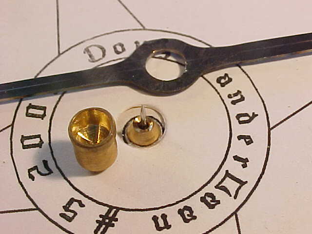
I took closeup pictures of the needle, bearing cup, and pivot pin. The largest picture file is only 34kB, so they won't take long to load.
6-1/2 inch compass needle, bearing cup hole, and phono needle pivot pin ..\Photos\crafts\Instruments\65in_01.JPG
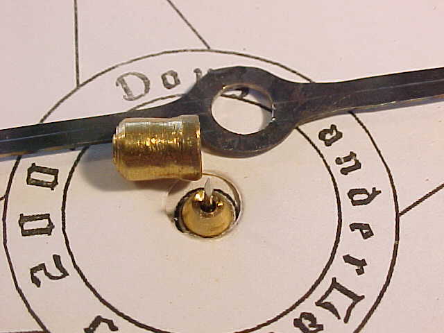
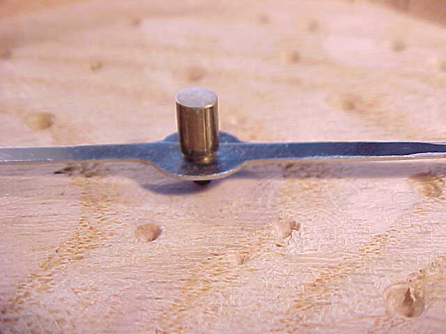
6-1/2 inch compass needle, bearing cup side, and pivot pin ..\Photos\crafts\Instruments\65in_02.JPG
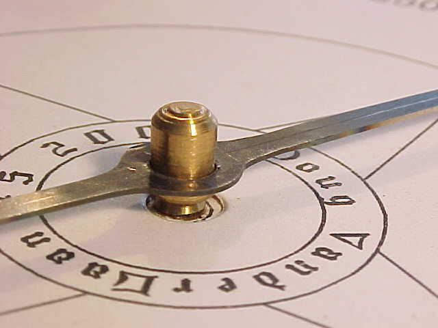
6-1/2 inch compass needle, bearing cup side, and pivot pin all assembled ..\Photos\crafts\Instruments\65in_03.JPG
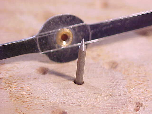
5 inch surveying compass needle, bearing cup side, and pivot pin ..\Photos\crafts\Instruments\50in_01.JPG
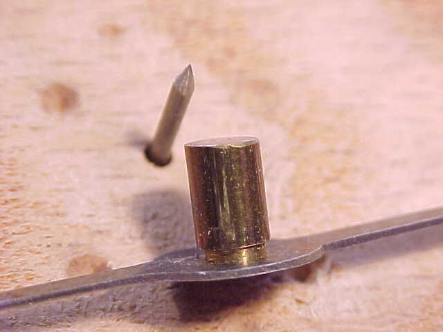
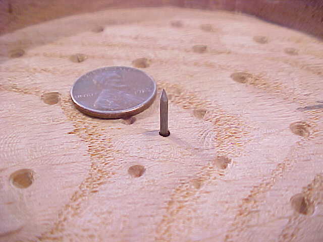
5 inch compass pivot pin made from tiny nail (with penny for scale) ..\Photos\crafts\Instruments\50in_02.JPG
5 inch compass needle, bearing cup side, and pivot pin all assembled ..\Photos\crafts\Instruments\50in_03.JPG
5 inch compass needle, bearing cup hole, and pivot pin ..\Photos\crafts\Instruments\50in_04.JPG
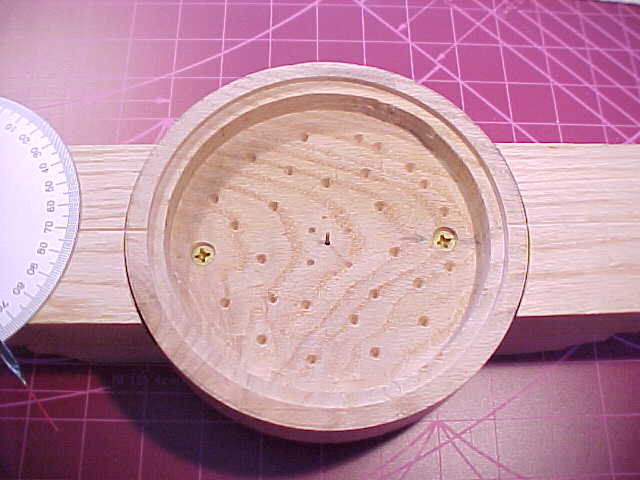
5 inch surveying compass "box" or frame and pivot pin ..\Photos\crafts\Instruments\50in_05.JPG
I made my compass "box" or frame out of scrap oak lumber scrounged from a packing crate or pallet frame. I drilled a small hole to mark the center and then hollowed out the space with a router. To reduce the routing work, I drilled out most of the waste wood with a Forstner bit in my drill press. Getting that interior nice and round was tricky, though. I left the wood in the very center until last so I could use the center hole as the locating point for a router circle guide to cut an even, smooth diameter as the vertical edge of the opening in the frame. Cutting the glass circle was also a challenge. I would recommend using plexiglass, like you can get from a hardware store for storm door window replacement.
Additional gathered information:
I've gathered an assortment of compass information from online historical books and assembled it all into a plain text file, downloadable here.
And in June, 2008, I found two very interesting articles by Jeffrey D Lock, with lots of color pictures, online from two different surveying magazines. Each is 7 or 8 pages long. One is from 'American Surveyor Magazine' of Fall, 2004. It is called Dividing_Ring_Article.PDF (this article should be available at www.colonialinstruments.com/im/pdf/Dividing_Ring_Article.pdf ).
The second is in the December, 2004 issue of 'Professional Surveryor' and is named 'Construction Details of Rittenhouse Compasses.PDF (and this article can be seen at http://www.colonialinstruments.com/im/pdf/Dividing_Ring_Article.pdf ).
Additionally, I have two ZIPped sets of AutoCad drawing files for compass roses and dials. They are NARROWS1.ZIP and COMPASS.ZIP
---home ---------- Created January 30, 2005 - updated July 26, 2009